POWER FACTOR AND POWER FACTOR CORRECTION
Long gone are the days when only engineers that worked with large electric motors and high power electric loads needed to worry about power factor. The introduction of switching power supplies into electronic systems has led to increasing international legislation, moving power factor up the list as a key concern for most engineers developing systems that run on ac mains power.
WHAT IS POWER FACTOR?
Defining Power Factor
Power factor (pf) is the ratio of real power (P) flowing to the load, to the apparent power in the circuit (S). It is a sinusoidal waveform and therefore expressed as dimensionless number between -1 and 1:
For a purely resistive load, the two figures are identical; for a reactive load the arithmetic for the apparent power produces the same figure, that is, the product of the RMS values of voltage and current. However, to find the actual (real) power delivered to the load, the instantaneous product of voltage and current must be integrated over the complete sine-wave cycle.
Adding Reactive Power Into the Equation
Real (or active) power, measured in watts (W), is defined as the circuit’s capacity to perform work at a given time. Apparent power, measured in volt amperes (VA), is the product of the current and voltage of the circuit.
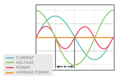
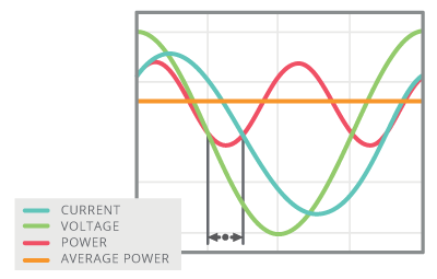
When current is leading or lagging voltage, the value of that integral will always be less than the value for the in-phase case over the same interval. This reflects the attribute of an inductor or a capacitor to act as energy stores; at various points through the ac cycle the reactive component (Q) is either storing energy, or returning it to the system.
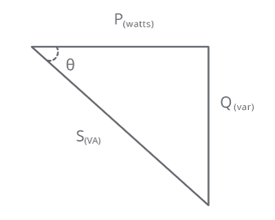
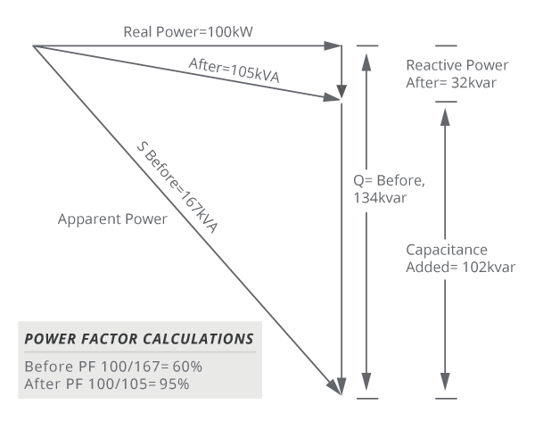
Perfectly sinusoidal waveforms follow Pythagoras, where the square of the apparent power is equal to the squares of the active power and reactive power measured in reactive volt amperes (var):
The relationship is conventionally visualized in a right-angled triangle vector diagram.
Apparent power is always greater than or equal to real power and a negative power factor can occur when the device starts to generate power that then flows back to the generator.
Ideal vs Real World
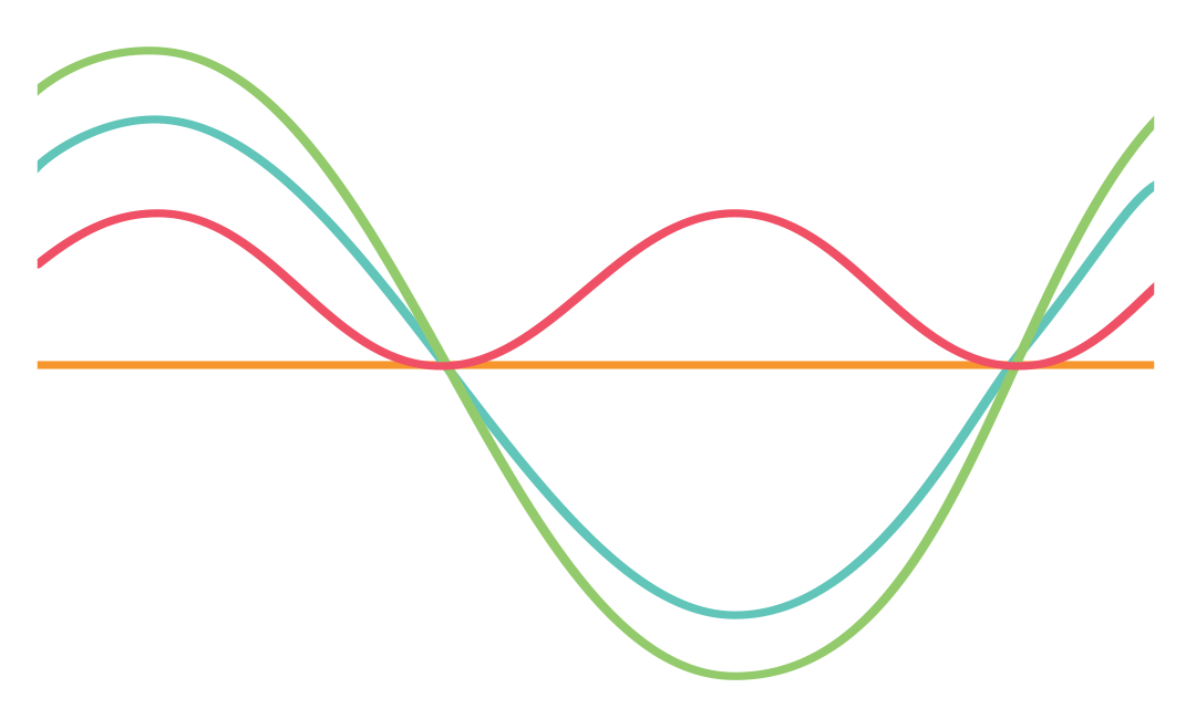
Ideal power factor occurs when the current and voltage waveforms are in phase:
When the power factor is not equal to 1.0, power losses, and potentially harmonics that disrupt other devices, occur.
Once again, this basic definition is for pure sinusoids. Non-sinusoidal waveforms are more complex, but as they can be represented by a series of harmonic sinusoids, the same basic principles apply. Problems occur, however, when a non-linear load on a power system, typically in the form of a power supply, create current harmonics not present in the voltage; in effect, these current harmonics become part of the reactive power. They do not represent true power delivered to the load, thus degrading the power factor.
THE NEED FOR POWER FACTOR CORRECTION
Importance of Power Factor and Power Factor Correction
Power factor is on the list of design concerns for designers of virtually every device that draws significant power from a mains socket, as well as for engineers in heavy-electrical sectors. Not only are there principles of good engineering practice at stake, there is also legislation to enforce conformance with power-factor norms.
Legislation
The first attempt to legislate for ac mains power interference came over 100 years ago (1899), to prevent incandescent lamps from flickering, but one of the key regulations came in 1978, with IEC 555-2 requiring power factor correction be incorporated into consumer products.
Today, the U.S. Department of Energy’s voluntary Energy Star guidelines call for computing equipment to have a power factor of ≥ 0.9 at 100 percent of rated output in the application’s power supply, meaning designs with internal power supplies require the use of active power factor correction.
Across the Atlantic, the EU legislates the EN 61000-3-2 standard for electronic equipment, setting limits to the 39th harmonic for equipment with input currents less than or equal to 16 A per phase. The standard is split into four classes: A, B, C for appliances, power tools, and lighting respectively, and the most stringent class, D, for PCs, computer monitors, and TVs rated between 75 and 600 W.

Following Europe’s lead, a host of countries are developing increasingly stringent legislation. Most notably China, Japan and Australia have government regulations for power-line harmonics that have evolved from EN 61000-3-2.
Supply Implications
Why is this cause for concern? Electric utilities and generating bodies require their customers to present a load to the power grid that is as nearly unity power-factor as possible. The main, but not the only reason, is fiscal. The customer expects to pay for the “real” work done on his premises – in other words, the value of W, above. But a PF of less than 1.0 means that the VA value must be higher than W.
The generators and transmission companies must provision to deliver the peak voltage and current values in the waveform at any time. A power factor of less than 1.0 is effectively an increase in their costs, and one that they pass back to customers by imposing an increased tariff for customers with low power-factor loads. Achieving maximum power factor is therefore a “win-win” for all concerned.
Engineering Problems of Low PF
There are further effects that power utilities must contend with, that makes a unity-power-factor load highly preferable. Rotating plant-generated power is more difficult to manage and to keep stable when supplying a low power factor, and there can be heating or overload hazards for transformers and transmission equipment in the supply grid. Grid stability is also more difficult to maintain with low-power-factor loads attached to the system. Low power factor also tends to be associated with other negative attributes for a well-behaved electrical load. Highly-distorted current waveforms drawn from the mains can inject high-order harmonics back into the supply grid.
Transmission equipment has higher losses at higher frequencies leading to heating problems, and, if the higher frequencies are present in the load placed directly on the generating plant, they can manifest themselves as destructive vibrations leading to excessive wear on components such as bearings. Current distortion can lead to out-of-balance currents in the neutral lines of 3-phase distribution networks, which in turn can take the neutral away from ground (voltage) and give rise to multiplicity of problems.
Poor Current Waveforms and Harmonic Effects
Waveform distortion is not, strictly, the same phenomenon as power factor but because of the close connection between the two (as noted above, current harmonics degrade PF), they are governed by the same standards that place limits on the load that may be drawn by mains-supplied equipment; for example EN 60555 in Europe, and IEC 555-2 internationally.
Power Supplies for Electronic Systems
Even when most electronic equipment was supplied by power supplies that used linear regulation, power factor (and waveform distortion) was often less than ideal, but was rarely addressed for anything other than the largest supplies. The typical, conventional off-line arrangement was that of a transformer followed by a bridge rectifier, feeding a reservoir capacitor. Conduction through the rectifier would take place when the dc voltage on the output line had sagged below the instantaneous value of the transformed ac supply, which could be for the complete cycle at full load, or only at the peak of the ac waveform under light load.
Switching Power Supplies
Switching power supplies can significantly worsen the situation. The off-line part of the design may not change, still comprising a transformer/rectifier, and capacitor, but now one or more switching regulators have been added to the equation. The input rectifier continues to generate poorly-shaped current waveforms with the added challenge that some of the higher-frequency switching noise from the regulation stage can find its way back into current drawn from the wall socket.
Phase and Harmonic Effects
Not only does this shift the effective current peak away from that of the voltage waveform in time, it also introduces high-harmonic-content switching waveforms that potentially worsen the distortion of the current waveform. The arrival of this class of supply broadly coincided with the widespread deployment of PCs and other IT products in great numbers. Such trends led directly to today’s legislative environment.
METHODS FOR POWER FACTOR CORRECTION
Passive vs Active Power Factor Correction
The solution to excess harmonics is to use power factor correction (PFC), which shapes the input current of the power supply to maximize the real power level from the mains and minimize harmonic distortion. Ideally, the electrical appliance should present a load that resembles a linear load, such as a simple resistor, rather than the reactive load of an uncorrected switching power supply. This corrected waveform minimizes losses as well as interference with other devices being powered from the same source.
Compensation for low power factor can be by passive or active devices. The simplest case is that of improving the power factor presented by electric motors. Naturally, being wound machines, they are highly inductive loads, and adding capacitors to the supply network has long been standard practice. Even this case may not be entirely simple; the designer of such a network has to take care not to create unwanted resonant effects, for example. Variable power factor in the load may be accommodated by an adaptive scheme to connect reactive elements as required and in high-power contexts (MW scale) rotating-machinery solutions can be applied.
Power supply designers must – subject to their designs falling into specific power rating bands – take into account regulatory constraints, but they are invariably also under pressure to meet space, component bill-of-materials and efficiency targets.
Passive Power Factor Correction
Passive power factor correction in the form of filtering can be effective, within limits, and has the effect of reducing the higher-order current harmonics that, as noted above, contribute to degraded power factor. Such techniques involve putting a low-pass filter in the input side of the power supply to suppress higher-order harmonic components, and then compensating lead/lag characteristics as with conventional power factor.
The downside to this scheme is that large (both by value, and physically) inductors and/or capacitors may be required. Additionally, there are limitations to the input range and power rating when implementing this scheme; passive PFC circuits are generally able to achieve a power factor in the range of 0.70-0.75.
Active Power Factor Correction
The existence of, and rapid progress in, high-speed, high-current capacity semiconductor switches – the same components that enable the high-efficiency switch-mode supply to be built at all – make available the option of active power factor correction which allows for a power factor close to 1.0.
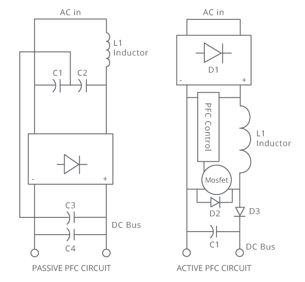
Because of this, it is the strategy that is most widely applied in present-day designs. A switching pre-regulator stage is placed in the input current path of the supply. That regulator is designed not only to maintain a constant dc voltage to feed the main converter stage of the power supply, but also to draw current from the input in-phase with the incoming ac voltage waveform.
An additional switching stage in the supply does impose some extra losses, and some extra cost. As indicated above, there are compensating savings in the form of smaller passive filtering components, and in the supply’s main converter. However, the added pre-regulator introduces a potential source of EMI (electromagnetic interference) noise that must be taken into account in the final design.
Design Constraints and Measurement
The design is therefore constrained by a power factor target, which will come from legislation and is non-negotiable, plus all of the usual factors of efficiency, component cost, and volume/board space occupied. To design to those targets, especially power factor, demands that it can be measured.
Simple multimeters will usually misread to some extent when presented with distorted waveforms; a good digital multimeter may make a good effort at reporting the RMS value of even a moderately distorted waveform, but will be challenged to record power factor. An oscilloscope with current and waveform probes can be used to gauge the phase-shift (of the angle θ, as above) but only if the voltage and current wave-shapes are reasonably similar. Electrical engineering has traditionally used precision electromechanical (moving coil) meters that directly measure power factor, but these are hardly suitable to track down the effects of kHz or MHz regulator switching in an advanced PSU.
A small number of test & measurement suppliers offer power analyzers; by rapidly sampling current and voltage waveforms and performing a suite of calculations – and applying a Fourier transform to extract harmonic information – every detail of a load’s performance in terms of distortion and power factor are revealed.
SUMMARY
Power factor is on the list of concerns for designers of virtually every device that draws significant power from a mains socket, as well as for engineers in heavy-electrical sectors. The power factor target, based on legislation, plus efficiency, component cost, and volume/board space need to be considered.
For this reason CUI has designed active power factor correction into the vast majority of its ac-dc power supplies rated at 100 W and above to help ease implementation and ensure compliance for OEMs.
