Negative Resistance and Why Your Dc-Dc Converter May Not Be Working Properly
March 30, 2021 by Bruce Rose - 7 Minute Read

Summary
If your dc-dc converter is not working and you’ve checked the obvious issues (not plugged in, not turned on, input fuse blown, etc.) the issue might be input impedance caused by negative resistance. A common solution is to either ac couple a resistance into the circuit or dc block the resistance from the circuit. This can be accomplished by placing the right capacitor as close as is reasonable to the input pins of the dc- converter.
Introduction
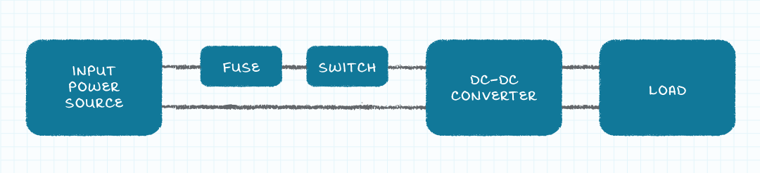
Many of us have had the experience where we purchased a dc-dc converter and it worked perfectly; ideally this is the norm. Unfortunately, most of us have also had the experience where a dc-dc converter does not work properly and we get to determine the source of the problem and an appropriate solution. The issue may be basic; the converter is not plugged in, the power is not turned on, or the input fuse is blown. The basic problems are all relatively easy to find and to solve. Too often with dc input switching supplies the situation is more complex; everything is connected properly, the simple problems have been eliminated, but the converter still does not produce the proper output voltage. In cases such as this, the problem may be the input impedance of the dc-dc converter interacting with the output impedance of the source supplying the power to the converter. When this impedance issue exists, the output voltage of the converter will have a significant ac component and the input voltage at the converter will also have a noticeable ac signal present.
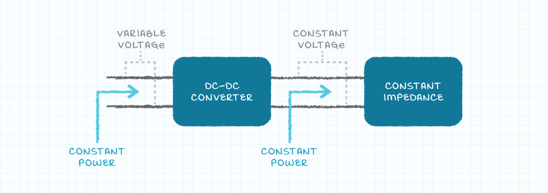
In order to simplify this discussion, we will consider a constant impedance load applied to the output of the dc-dc converter. The power supplied to the constant impedance load is also constant because the output voltage from the dc-dc converter is constant. The constant power supplied to the output load means a constant power is drawn by the input of the converter. Now the fun begins! We have created a power load (the dc-dc converter with a constant output power load) which draws constant power, independent of the applied voltage (the load on the dc-dc converter is constant and the power conversion efficiency is constant, thus the power drawn by the input of the converter is constant). As we will see, it is an interesting situation to have a load drawing constant power independent of the applied voltage.
Negative Resistance
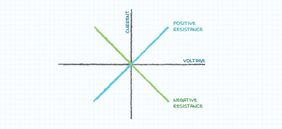
With this style of load, as the input voltage applied to the dc-dc converter rises the input current falls and as the input voltage applied to the converter falls the input current rises. The situation of the incremental current and voltage moving in opposite directions is the behavior of a negative incremental resistance. With a more familiar positive incremental resistance a rise in applied voltage results in a rise in applied current and a fall in applied voltage results in a fall in applied current.
Oscillations
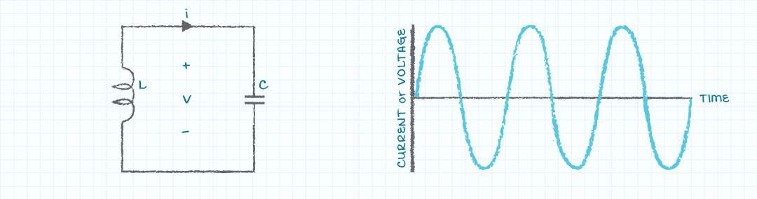
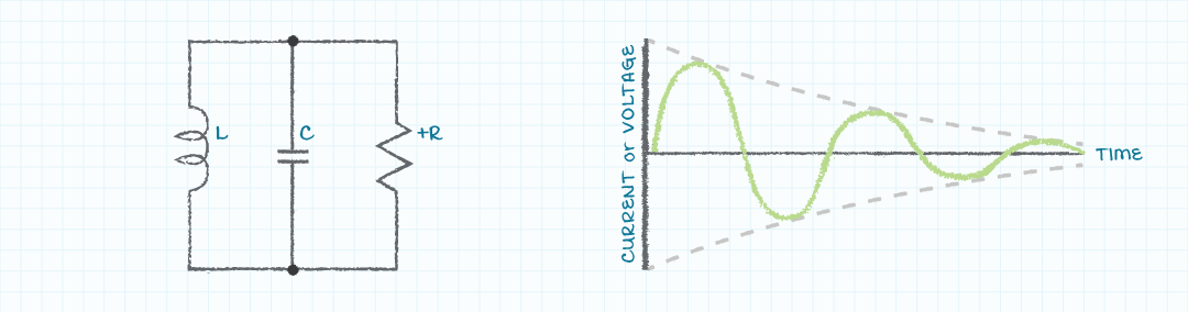
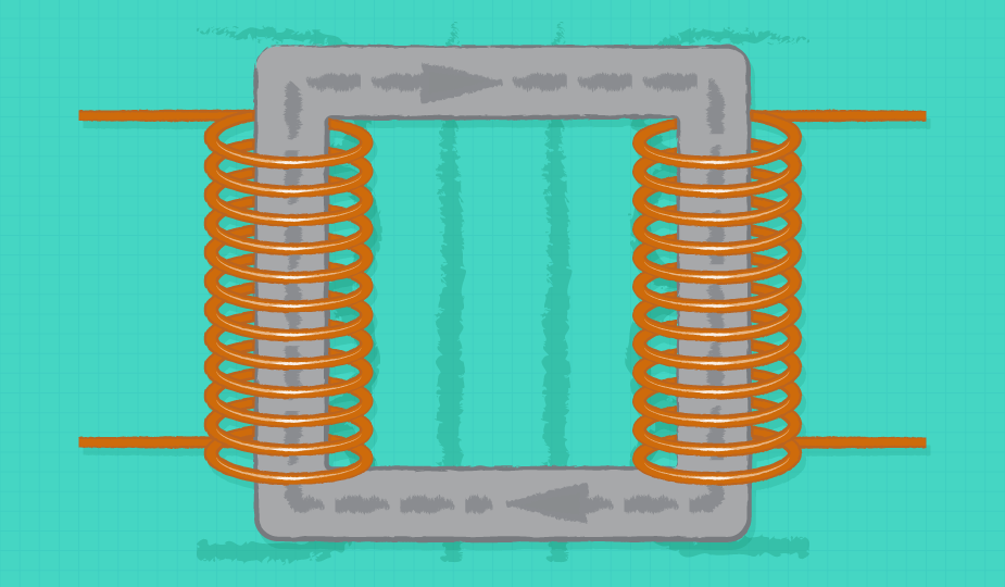
We will now discuss one of the potential effects of having a negative incremental input resistance. It will be helpful to understand the behavior of a circuit comprised of a capacitor and an inductor. If energy is applied to the capacitor and inductor circuit, the energy will swap between the electric field associated with the capacitor (voltage across the capacitor) and the magnetic field associated with the inductor (current through the inductor). This swapping of the energy will appear as a sinusoidal voltage across the elements and current flowing through the elements, the behavior of an oscillating circuit.
In real circuits with capacitors and inductors, there is also parasitic resistance associated with the components. This parasitic resistance will dissipate energy and the oscillation will eventually cease.
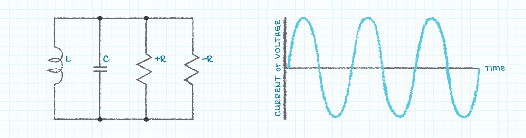
Negative Resistance and Oscillations
If negative resistance is added to the R-L-C circuit it can cancel the positive resistance and create a circuit with zero resistance and the oscillation can continue. The circuit with capacitance, inductance, and zero resistance can happen under particular operating conditions right (or wrong) at the input of dc-dc converters. The oscillation will be sustained when the negative input impedance of the dc-dc converter cancels the positive impedance of the associated capacitance and inductance.
It should be understood, the capacitance and inductance of the circuit can be physical elements (intentional or parasitic) or can be synthesized by the output impedance of the power source and the input impedance of the dc-dc converter. The synthesized negative resistance and possibly synthesized reactive elements have characteristics such that as the system operating conditions change the values of the synthesized elements also change. One challenge with this situation is that it is difficult to accurately model the system associated with the dc-dc converter to determine under what operating conditions the oscillation will occur. Another challenge with this situation is the occurrence of the oscillation will exist under certain operating conditions and the oscillation will not be present during other operating conditions.
Positive Resistance to Dampen Oscillations
Although it may be difficult to predict the operating conditions which will cause the oscillation, it is relatively easy to add positive resistance between the output of the power source and the input of the dc-dc converter such that an oscillation is not sustained. Two options for adding resistance are to place a resistive element in series between the power source and the dc-dc converter or to place a resistive element in shunt across the output of the power source and the input to the dc-dc converter. Unfortunately, the power dissipated by either of these solutions often is too large to be acceptable. A third solution that is commonly used is to ac couple a resistance into the circuit or dc block the resistance from the circuit. The benefit of this coupling or blocking is the resistance affects ac signals (the oscillation) and does not affect dc signals (desired power flow). One method to implement this desired resistance is to place an electrolytic capacitor with a large capacitive value (tens to hundreds of micro Farads, depending upon the power levels) as close as is reasonable to the input pins of the dc-dc converter. The equivalent series resistance (ESR) of the capacitor is ac coupled into the circuit and serves to dissipate sufficient energy to prevent sustained oscillation but is blocked from the dc power path and thus does not dissipate energy associated with the dc flow of power.
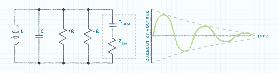
The ESR of the capacitance needs to be small enough to not dissipate excessive power and large enough to effectively dampen oscillations. The most commonly available electrolytic capacitors have the correct amount of ESR to serve in this application. Extremely low-cost electrolytic capacitors may have an ESR which is too high and thus causes excessive power dissipation. Extremely high-cost electrolytic capacitors, film capacitors, and ceramic capacitors all have ESR values that may be too low to properly dampen the oscillations.
Conclusion
This discussion has been a practical overview of how to prevent oscillations on the input of dc-dc converters. For theoretical discussions of the input impedance of dc-dc converters and the output impedance of voltage sources check out Venable Instrument's Source-Load Impedance Analysis.
Fundamentals , Testing & Failure Analysis
You May Also Like
Have comments regarding this post or topics that you would like to see us cover in the future?
Send us an email at powerblog@cui.com


Bruce Rose
During his many years in the electronics industry working in design, sales, and marketing, Bruce Rose has focused on analog circuits and power delivery. His range of work experience includes organizing and chairing international workshops, publishing and presenting in more than 40 technical conferences and journals, and having been awarded seven patents. While he enjoys his time at work, Bruce further enjoys the time he is able to spend with his family hiking, biking, and canoeing as well as pursuing his passion of full scale and model aviation.