What is the Difference Between Unregulated and Regulated Power Supplies?
February 4, 2020 by Ron Stull - 7 Minute Read
One of the primary functions of a power supply is to convert an input voltage to a desired output voltage. How accurate this voltage is and how much it varies under changing conditions depends on whether the output is regulated and if so, to what degree. When selecting a power supply it is important to understand what regulation is and whether or not it is needed for a particular application.
Background
Regulation is the act of controlling something; in power supplies this typically means controlling the output voltage. To understand its importance and how it works, first consider the circuit in Figure 1.
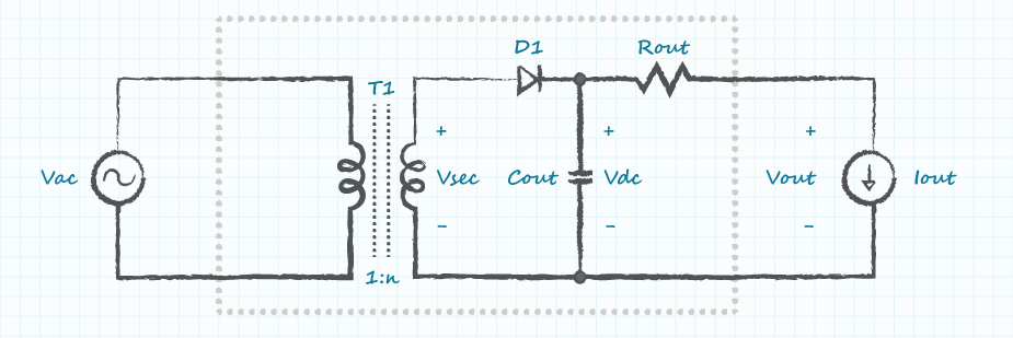
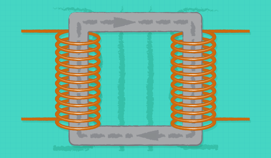
The circuit in Figure 1 shows a basic linear unregulated dc-dc converter, which works in the following way:
- The ac input voltage is applied across the primary of T1
- The transformer outputs the secondary voltage, Vsec, which is equal to Vac multiplied by the turns ratio, n (Equation 1)
- The combination of D1 and Cout convert Vsec to a dc voltage, Vdc, equal to the peak of Vsec
- The output voltage, Vout, is then equal to the Vdc minus losses in Rout due to Iout (Equation 2)
Vout = √2 * Vsec - Iout * Rout
The first thing to notice in these equations is that any change to the input voltage will directly affect the output voltage. If Rout is ignored, then Vout is equal to the peak of Vin times the turns ratio. In applications with an input that varies this can lead to large changes in the output voltage. For example, if Vout were 12V with an ac input of 120V and we were to double the input to 240V, Vout would also double to 24V.
In addition to being affected by changes to the input, the load will also affect the output voltage. Rout (which is due to items such as cabling, PCB traces, transformer impedances, etc.) causes a voltage drop between Vdc and Vout that is proportional to the load current. At no load, 0A, Vdc is equal to Vout, but as Iout increases, so does the voltages across Rout, causing Vout to fall. For example, if Vdc were 12V and Rout was 1 ohm, as Iout increased from 0 to 1A the voltage across Rout would increase from 0V to 1V and Vout would fall from 12V to 11V as a result.
The dependencies on input voltage and load conditions, specified in datasheets as line and load regulation respectively, lead to wide variations in output voltage as the conditions change. Some applications may be able to handle this, but many require tighter tolerances under a wide range of conditions. For these applications, regulation is required.
Figure 2 shows a simplified linear regulator which can be added in between the load and Rout of Figure 1, used to regulate the output voltage of Figure 1.
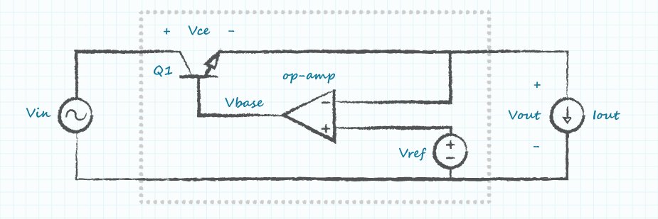
This regulator of Figure 2 works in the following way. Vout is equal to the input voltage minus the voltage drop across the collector and emitter of Q1, Vce (Equation 3). The op-amp compares Vout to a reference voltage, Vref, and then amplifies the difference (Equation 4).
Vbase = gain * (Vref - Vout)
This creates a negative feedback loop. Equation 4 shows that if Vout is greater than Vref, Vbase goes negative, turning off Q1 and causing Vce to increase. By increasing Vce, Vout is brought down towards the reference voltage. If the voltage were then to fall below the reference voltage, Vbase would turn positive and turn Q1 back on, decreasing Vce and bringing Vout back up. In this way, the regulator is able to maintain a constant Vout under changing line and load conditions.
The linear power supply and regulator were chosen for the previous examples for simplicity, however due to their inefficiencies they are often replaced by more complex switching power supplies. Even with the added complexity in switching power supplies, the fundamental way in which they regulate is the same. The main difference with how they regulate is the control variable. Both linear and switching regulators compare the output to a reference and use this information to control some aspect of the circuit. In the case of the linear regulator, the voltage across a transistor was used to regulate Vout. For many switching regulators the duty ratio (ratio of switch on-time to total switching period) is controlled. In other topologies, such as the resonant LLC, it is the switching frequency that is controlled.
Because the components used to create the feedback loop and references aren’t perfect, neither is the regulation. Datasheets for power supplies, including the unregulated ones, will include some form of information informing the user how much the output voltage can be expected to change under a range of conditions. Sometimes a single number is given as either total regulation or just regulation, which encompasses all conditions. It is also common to see the two listed separately, indicating how much the output will change with respect to a single condition (i.e. Input voltage or Load).
Now, knowing what regulation does and how it works, how do you know which one you need for your application?
Regulated
As discussed earlier, the output of unregulated power supplies is heavily dependent upon the operating conditions. The only way to improve the tolerance on the output is to limit the range of operating conditions. For applications that must accept a wide range of conditions, such as a power supply with a universal input (90 ~ 265 Vac), and/or those that require a tight tolerance on the output voltage, regulation is required.
Even in applications where the range of conditions is narrow, differences in component tolerances and temperature can lead to differences in output voltage from converter to converter. This is usually specified in datasheets as set-point accuracy. Even if the conditions are constant and the output voltage doesn’t change, without regulation the output voltage may still fall outside of the required tolerance range.
Unregulated
Applications with a narrow range of operating conditions and/or that can accept a wide range of voltages may see some benefit from using an unregulated dc-dc converter. The two primary benefits of an unregulated dc-dc converter compared to that of a regulated converter are size and cost; unregulated converters are often smaller and less expensive than equivalent regulated converters. This is the result of the extra components required to create the feedback loop.
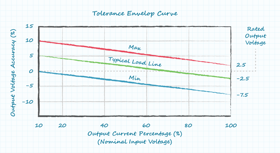
When selecting an unregulated dc-dc converter, the manufacturer will often supply graphs to show the relationship between the output and line and load conditions. The user should inspect these graphs and verify that the voltage is within their limits for all operating conditions. The graph in Figure 3 is one such graph and shows three curves. The min and max lines indicate the set-point accuracy. An individual converter will fall in between these lines with a load line parallel to these curves. The load line shows how much the output voltage can be expected to change as the load goes from min to max.
Conclusion
A tightly controlled voltage is important in many applications. Regulated dc-dc converters can provide tight tolerances over output voltages under a wide range of operating conditions. However, for those applications where a tightly controlled voltage isn’t necessary, it may be beneficial to use an un-regulated dc-dc converter. In these cases, the designer may be able to reduce size and cost by using an un-regulated dc-dc converter.
Fundamentals , Product Selection
You May Also Like
Have comments regarding this post or topics that you would like to see us cover in the future?
Send us an email at powerblog@cui.com


Ron Stull
Ron Stull has gathered a range of knowledge and experience in the areas of analog and digital power as well as ac-dc and dc-dc power conversion since joining CUI in 2009. He has played a key role on CUI’s Engineering team with responsibilities including application support, test and validation, and design. Outside of power engineering Ron can be found playing guitar, running, and touring the outdoors with his wife, where their goal is to visit all of the U.S. National Parks.